GPT Surface Pump Catalog
Positive Displacement Plunger Pump Packages
Engineered Application’s for
Water Injection / Disposal
Jet Pumping
Fluid Transfer
Rental or Purchase
Plunger Pump Specifications
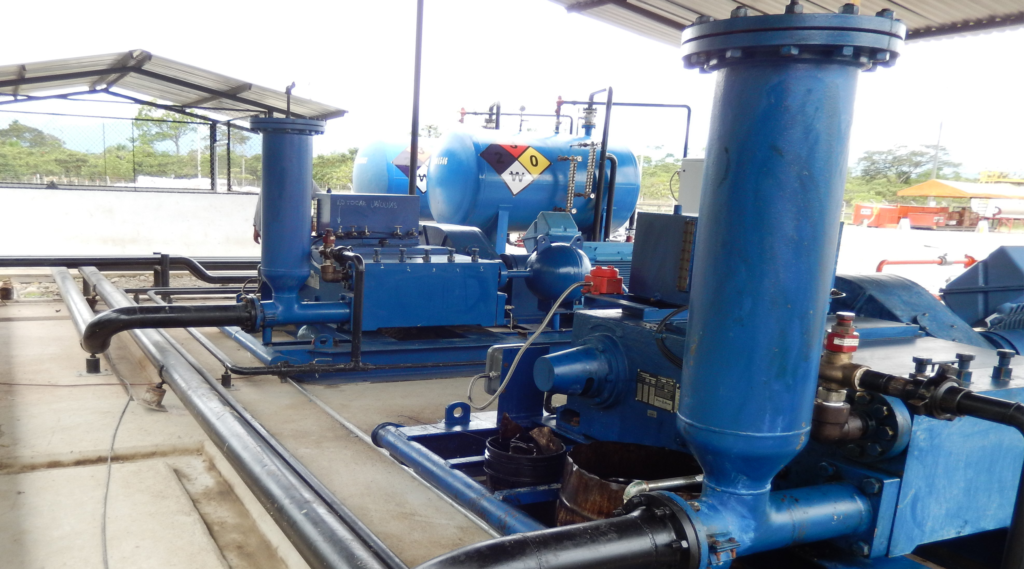
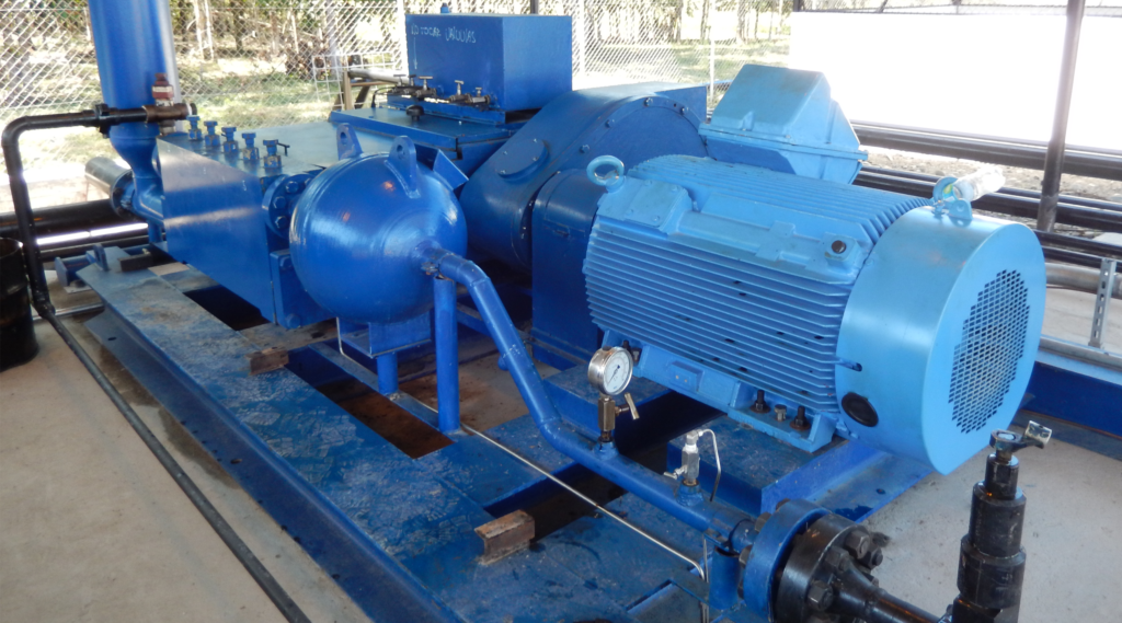
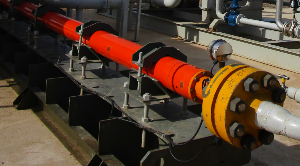
Global Petroleum Technologies, provides a reliable single acting positive displacement reciprocating plunger pump package with direct drive or belt drive designed and fabricated with ancillary equipment to provide low maintenance service. The plunger pump is a proven design that is supported with large inventories of spare parts around the world because its parts are 100% interchangeable with many pumps in the industry. This workhorse design has been providing reliable service for decades.
General Specifications
Fluid end and valve covers: Aluminum Bronze
Stuffing box: Stainless steel
Stuffing box internals: Aluminum bronze
Plungers: Tungsten carbide
Packing: Kevlar spring loaded
Intermediate rods: Stainless steel
Lubrication: Splash type if speed above 200 rpm
100 Horsepower Triplex Pump
- Stroke Length: 4″
- Rated: 100 horsepower at 450 rpm
- Rated Plunger Load (lbs): 6595 lbs
- M fluid end: Suction: 3″ ANSI 150# FF, Discharge: 1-1/2″ API 5000#
- RTJ H fluid end: Suction: 3″ ANSI 300# FF, Discharge: 1-1/2″ API 5000# RTJ
|
|
|
| 100-M Fluid End |
|
|
|
| |
Plunger size, in. | Plunger area in² | Max.Pressure | BPD/RPM | 200 rpm | 250 rpm | 300 rpm | 350 rpm | 400 rpm | 450 rpm |
1-3/4 | 2.4053 | 2744 | 4.2858 | 857 | 1071 | 1286 | 1500 | 1714 | 1929 |
1-7/8 | 2.76 | 2388 | 4.92 | 984 | 1230 | 1476 | 1722 | 1968 | 2214 |
2 | 3.1416 | 2101 | 5.5978 | 1120 | 1399 | 1679 | 1959 | 2239 | 2519 |
|
|
|
| 100-H Fluid End |
|
|
|
| |
1-1/4 | 1.2272 | 5000 | 2.1866 | 437 | 547 | 656 | 765 | 875 | 984 |
1-1/2 | 1.7672 | 3735 | 3.1487 | 630 | 787 | 945 | 1102 | 1259 | 1417 |
1-3/4 | 2.4053 | 2744 | 4.2858 | 857 | 1071 | 1286 | 1500 | 1714 | 1929 |
165 Horsepower Triplex Pump
- Stroke Length: 5″
- Rated: 165 horsepower at 400 rpm Rated Plunger Load (lbs.): 9800 lbs.
- M fluid end: Suction: 4” ANSI 150# FF, Discharge: 2” API 5000# RTJ
- H fluid end: Suction: 3” API 2000# RTJ, Discharge: 2” API 5000# RTJ
|
|
|
| 165- M Fluid End |
|
|
|
| |
Plunger size, in. | Plunger area in² | Max. Pressure | BPD/RPM | 150 rpm | 200 rpm | 250 rpm | 300 rpm | 350 rpm | 400 rpm |
2 | 3.1416 | 3120 | 6.9972 | 1050 | 1399 | 1749 | 2099 | 2449 | 2799 |
2-1/4 | 3.9761 | 2465 | 8.8558 | 1328 | 1771 | 2214 | 2657 | 3100 | 3542 |
2-1/2 | 4.9088 | 2000 | 10.9331 | 1640 | 2187 | 2733 | 3280 | 3827 | 4373 |
2-3/4 | 5.9396 | 1650 | 13.2291 | 1984 | 2646 | 3307 | 3969 | 4630 | 5292 |
|
|
|
| 165- H Fluid End |
|
|
|
| |
1-1/2 | 1.7672 | 5000 | 3.9359 | 590 | 787 | 984 | 1181 | 1378 | 1574 |
1-3/4 | 2.4053 | 4075 | 5.3575 | 804 | 1071 | 1339 | 1607 | 1875 | 2143 |
1-7/8 | 2.76 | 3550 | 6.153 | 923 | 1231 | 1538 | 1846 | 2154 | 2461 |
2 | 3.1416 | 3120 | 6.9972 | 1050 | 1399 | 1749 | 2099 | 2449 | 2799 |
200 Horsepower Triplex Pump
- Stroke Length: 5″
- Rated: 200 horsepower at 400 rpm
- Rated Plunger Load (lbs.): 11870 lbs.
- M fluid end: Suction: 4” ANSI 150# FF, Discharge: 2” API 5000# RTJ
- H fluid end: Suction: 3” API 2000# RTJ, Discharge: 2” API 5000# RTJ
|
|
|
| 200-M Fluid End |
|
|
|
| |
Plunger size, in. | Plunger area in² | Max. Pressure | BPD/RPM | 150 rpm | 200 rpm | 250 rpm | 300 rpm | 350 rpm | 400 rpm |
2-1/4 | 3.9761 | 2988 | 8.8558 | 1328 | 1771 | 2214 | 2657 | 3100 | 3542 |
2-1/2 | 4.9088 | 2419 | 10.9331 | 1640 | 2187 | 2733 | 3280 | 3827 | 4373 |
2-3/4 | 5.9396 | 2000 | 13.2291 | 1984 | 2646 | 3307 | 3969 | 4630 | 5292 |
|
|
|
| 200-H Fluid End |
|
|
|
| |
1-1/2 | 1.7672 | 5000 | 3.9359 | 590 | 787 | 984 | 1181 | 1378 | 1574 |
1-3/4 | 2.4053 | 4938 | 5.3572 | 804 | 1071 | 1339 | 1607 | 1875 | 2143 |
1-7/8 | 1.76 | 4300 | 6.153 | 923 | 1231 | 1538 | 1846 | 2154 | 2461 |
2 | 3.1416 | 3780 | 6.9972 | 1050 | 1399 | 1749 | 2099 | 2449 | 2799 |
300 Horsepower Triplex Pump
- Stroke Length: 5″
- Rated: 300 horsepower at 400 rpm
- Rated Plunger Load (lbs.): 10700 lbs.
- M fluid end: Suction: 6” NSD 600# RTJ, Discharge: 3” NSD 5000# RTJ
- H fluid end: Suction: 6” ANSI 600# RTJ, Discharge: 2” ANSI 2500# RTJ
|
|
|
| M Fluid End |
|
|
|
| |
Plunger size, in. | Plunger area in² | Max. Pressure | BPD/RPM | 150 rpm | 200 rpm | 250 rpm | 300 rpm | 350 rpm | 400 rpm |
2 | 3.1416 | 3400 | 11.6620 | 1749 | 2332 | 2916 | 3499 | 4082 | 4665 |
2-1/4 | 3.9761 | 2690 | 14.7597 | 2214 | 2952 | 3690 | 4428 | 5166 | 5904 |
2-1/2 | 4.9088 | 2185 | 18.2219 | 2733 | 3644 | 4555 | 5467 | 6378 | 7289 |
2-3/4 | 5.9396 | 1800 | 22.0485 | 3307 | 4410 | 5512 | 6615 | 7717 | 8819 |
|
|
|
| H Fluid End |
|
|
|
| |
1-1/2 | 1.7672 | 5000 | 6.5599 | 984 | 1312 | 1640 | 1968 | 2296 | 2624 |
1-3/4 | 2.4053 | 4450 | 8.9287 | 1339 | 1786 | 2232 | 2679 | 3125 | 3571 |
1-7/8 | 2.76 | 3875 | 10.25 | 1537 | 2050 | 2663 | 3075 | 3588 | 4100 |
2 | 3.1416 | 3400 | 11.6620 | 1749 | 2332 | 2916 | 3499 | 4082 | 4665 |
Ancillary Equipment
- The following ancillary equipment should be considered when selecting a plunger pump application.
1. Suction Stabilizer: The suction stabilizer is highly recommended for all plunger pump applications to minimize vibration and cavitation that can result in frequent failures. The suction stabilizer minimizes effects of acceleration head piping requirements that are based on pump operating conditions, suction pipe length, diameter and design. The suction stabilizer has an inlet and outlet connection the same or larger than the pump suction inlet and is designed to handle the full capacity of the pump.
2. Discharge Dampener: The intensity of low frequency pulsations related to plunger pump discharge flow is greatly decreased with a properly designed pulsation dampener. Discharge piping problems can result in expensive failures that create environmental issues. GPT offers technical assistance to diagnose pipe vibrations and failures and designs new systems for reliable trouble-free service.
3. Pressure safety valve (PSV): All plunger pumps must be equipped with an emergency pressure relieve valve that releases pressure in the event of a valve closure or system or piping failure.
4. Shut off valves: Suction and discharge piping should be equipped with shut off valves of equal diameter and pressure rating of the pump. Full opening ball valves are common in this application.
5. Drain valves: Drain valve on the suction and discharge are required to drain the pump when servicing. The valve can also serve for installation of suction and discharge pressure gauges or transmitters. Needle valves are commonly used in this application.
6. By-pass valve: A by-pass loop and shut off valve is required on multiple pump installations to allow a pump to start up under no load so lubricant can get to load carrying surfaces.
7. Check valve: A check valve is recommended in multiple pump installations to keep high pressure fluid from the pump when shut down.
8. By-Pass Pressure Control Valve: Application where constant pressure is critical to operation such as in jet pumping, a by-pass pressure control valve should be installed to release fluid not required by the jet pump and absorb lift discrepancies in continuous operation. These valves should by-pass less than 1000 bpd fort optimum life.
9. Flow Meter: Turbine flow meters can be added to the discharge of the pump to monitor flow rates.
10. Instrumentation: The following are the most common instrumentation on pump packages.
Discharge pressure switch gauge or transmitter Suction pressure switch gauge or transmitter
Oil level switch gauge
Oil Temperature switch gauge or transmitter
Pump Vibration switch gauge or transmitter
Gear Reducer Vibration switch gauge or transmitter
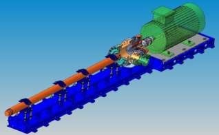
Horizontal Pump System Specification
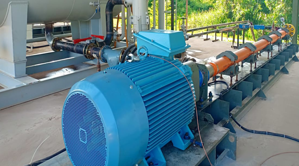
Global Petroleum Technologies provides complete horizontal pumping systems (HPS) complete with installation and technical assistance to insure reliable service. GPT engineers have years of experience designing and installation complete process systems as well as operating and repairing HPS units. That experience results in technical support to provide minimum down time and maintenance cost.
HPS units do not have the casing diameter restrictions that limits the ESP, so GPT choses pump with the greatest diameter shafts to provide greater support. Torque chambers can be equipped with mechanical seals, cooling or support system to insure reliable service with minimum down time.

HPS Specifications
Model | Target Capacity, BPD | Target Pressure Discharge/ Suction | Capacity BPD/ rpm | Pump OD |
NRV3800 | 6,000 | 4000/ 50 | 4700 bpd@ 2910 rpm 6300 bpd @ 3880 rpm | 6.77 |
NP | 10,000 | 2500/ 50 | 7900 bpd @ 3640 rpm 10,100 bpd @ 4660 rpm | 5.35 |
HPS equipment include industrial electric motor, thrust chamber, centrifugal pump, accessories and instrumentation. The pump is rated at 3600 rpm.
Stages: Powder technology mixes raw materials in order to obtain specific type of stages with special features.
| Table | Abrasion resistance | |
| Abbr. | Full name | Descrption |
| AR1 | Abrasion Resistant 1 | For fluid containing solids up to 175 ptb (500 mg/I) Note: Applicable for all Floater pumps and all pumps of NR and NT series |
Pump Shaft: The shaft material is selected according required power at maximum flow rate.

Shaft material and yield strength:
| S8 | Stainless Steel | (785 MPa) |
| S11 | Stainless Steel | (1080 MPa) |
| S13 | Stainless Steel | (1275 MPa) |
| S14 | Stainless Steel | (1370 MPa) |
| S16 | Stainless Steel | (1570 MPa) |
| M8 | Monel Alloy | (785 MPa) |
| I8 | Inconel Alloy | (785 MPa) |
| I11 | Inconel Alloy | (1080 MPa) |
| I13 | Inconel Alloy | (1275 MPa) |
| I14 | Inconel Alloy | (1370 MPa) |
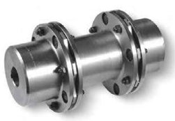
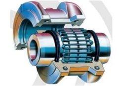
Coupling
The motor coupling considered for conventional HPS units (electric motor) connects and transmits torque from electric motor to thrust chamber. The coupling is selected based on motor power and shaft sizes. This coupling provides high reliability with simplified serviceability.
The coupling selected for this application is GRID COUPLING.
Thrust Chamber
The thrust chamber was designed to absorb the axial thrust generated by fluid displacement in dynamic conditions. In the other hand, transmits torque and power from electric motor to pump.
In this thrust chamber model, the axial thrust generated is absorbed by bearing located in the rear side of the thrust chamber.
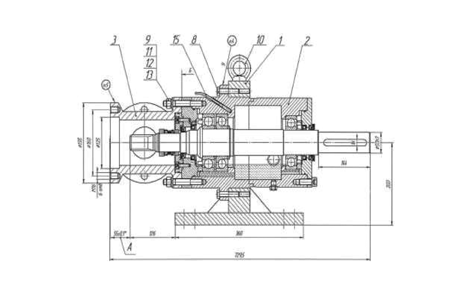
The chamber suction is designed according ASME B16.5 standard, it has a short shaft that connects thrust chamber with first pump. The mechanical seal is mounted on thrust chamber shaft and its main roll is isolation of the fluid from environment. The “short shaft” design expedites installation and uninstallation of the mechanical seal.
Suction Chamber
The suction chamber is designed according ASME B16.5 standard, it has a short shaft that connects thrust chamber with first pump.
The mechanical seal is mounted on thrust chamber shaft and its main roll is isolation of the fluid from environment.
The “short shaft” design expedites installation and uninstallation of the mechanical seal.
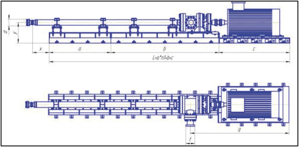
Skid
The Skid will hold the HSPS components. A suitable structural analysis let us to obtain robust frame design with provisions for dampening vibrations that typically occur over time, additionally this will support the demanding applications.
The modular skid design allows easily accommodate to changing duty conditions or the redeployment of an existing HSPS unit for an entirely different application.
The extensions skid and pump support designs give to specific equipment the versatility to cover new operating conditions and to avoid replacing all the components.
Electric Motors
Industry standard electric foot mounted motors are used as the primary driver for the Horizontal Pumping Systems.
The operator should indicate the following specifications
- Supply voltage: Common: 480- VAC
- Supply frequency: Common 60 hertz
- Motor phase: Common 3 phase
- Temperature class:
- Class: Group: and Division: Common: Class 1 group C&D Div. 2 (TEFC)
- Insulation class: Common F
Equations, Conversion and Useful Information
- 1 Cubic meter per day = 8.38641436 Fluid barrels per day.
- 1 Barrel = 159 liters = 42 gallons
- 1 Bpd = .159 cubic meters pe day
- 1 Barrel = 5.61458
- 1 Horsepower -0.7457 Kilowatts
- HP = Torque x RPM / 5252
- GOR: 1 scf/bbl = 0.18 m3/m3
- Hydraulic horsepower = (pressure differential x bpd) /58,800
Net Positive Suction Head for GPT Plunger Pumps
NPSHR = Function of Pp + Pv + Pf – Pa + Ha
Where
- NPSHR: Net Positive Suction Head Required
- Pa: Atmospheric pressure in psia (+/- 14 psia)
- Pv: Vapor Pressure of the fluid, in psia
- Pf: Pressure drop due to friction in suction piping and fittings, in psia (normally below .1 psig= 14.1 psig)
- Ha: Acceleration head in feet. (see calculation below)
- Pp: Pressure required by pump above vapor pressure to fill pump with acceptable efficiency, in psi. A factor of pump internals such as valve springs, internal passages etc…) The pump manufacturer specifies 3.5 psig = 17.5 psia
Acceleration Head: Ha= (CLNQ) / D2
- C: Triplex = .000598, C: Quintuplex = .000362
- L: Suction tubing length in feet
- N: rpm pump speed
- Q: gpm pump capacity at operating speed
- D: suction tubing diameter