Artificial Lift Solutions with Jet Pumps
A complete Jet Pump Product Line
The New Generation Jet Pump
Cost Effective
Global Petroleum Technologies, GPT optimized the jet pump system to provide the most reliable, cost effective design available today.
Adaptive Technology
Modern technology and computerized mathematical modeling have taken huge steps in the last 20 years while the jet pump system has remained unchanged, but the oil industry strives more today than ever before to find ways to produce oil at low cost. GPT went through the complete jet pump lift system to make it more efficient, effective and reliable to meet the change of producing oil at lower cost.
Range of Application
Jet pumps offer a variety of well completion solutions that often exceed limitations often stated in textbooks. Ranges require specific completion and often two limits are not possible with the same completion.
|
Tubing |
1.66” |
2-3/8” |
2-7/8” |
3-1/2” |
|
Depth, ft. |
7000’ |
10,000’ |
20,000’ |
20,000’ |
|
Production bpd |
500 |
|
20,000 |
20,000 |
|
API |
25° |
8° |
8° |
8° |
Jet pumps can be a short as 24” so well deviation is not an issue as long as the pump can be circulated to bottom. Corrosion can be mitigated with chemicals in the power fluid to treat everything above the standing valve while all jet pump components can be manufactured in stainless steels with high temperature seals.
Artificial lift Today
The challenges of unconventional reservoirs include well bore geometries, rapidly changing reservoir pressures, production rates, multiple well pads, gas and sand production. Traditional artificial lift methods have not done the job and many operators are moving toward gas lift, but where gas lift is not the answer, the jet pump offers very similar benefits to gas lift. GPT new generation lift systems deliver a cost-effective edge for maximum production and revenue. GPT can provide multiple lift solutions that can be run in the well in a single completion to pump the well from flow back to maturity.
Jet Pumps
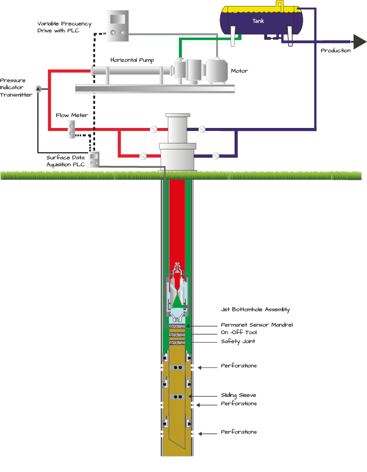
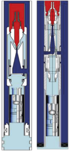
Textbooks introduce jet pumps with what is called a casing free jet pump completion. The term comes from the fact that the pump is free to float or circulate in and out of the well and that production flows up the casing annulus. It is also the most common jet pump installation offered by vendors, but not always the best solution. The production engineer should know features and limitations of the available completions in jet pumping. In casing free completions, high pressure fluid is injected down the production tubing and a casing packer isolates the casing annulus, so production enters below the packer to the jet pump. All well fluids and gas flow through the pump. A standing valve below the pump prevent fluid loss when shut down.
This completion is great for initial stages of frac fluid recovery with limited gas production and higher-pressure reservoirs or active aquifers. The best performance is obtained with pump intake pressure above the bubble point and greater than 100 psi per thousand feet of depth.
There are several models of jet pumps with different features and ranges of production capacity that is based in internal flow capacity. The high-volume jet pump in 2-7/8” tubing has produced at rates exceeding 20,000 bpd while the lower cost standard jet pump begins to incur abnormal internal pressure losses with power fluid flow rates above 2500 bpd. More on jet pump models later in the catalog.
Surface System
Fluid and gas flowing from the well can be processed through a well site pressurized vessel system that can be designed to separate oil, water, gas and solids.
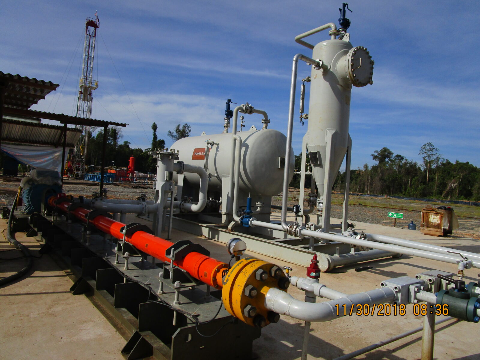
New computer aided process modeling helps power fluid treatment provide more effective results. This is especially helpful in sand removal.
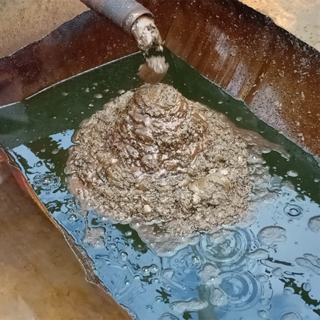
Figure 4.0 shows the sand removal efficiency of the GPT New Generation Well Site Power Fluid Treatment System. These applications and others confirm that jet pumps can produce more than 10 pounds per barrel reliably. There are applications where the jet pump is used to remove sand from sanded well bores. The problem is normally sand handling at the surface that can be mitigated with the new process systems.
The well site power fluid process system must also provide the necessary suction conditions for the surface power pump.
Production is sent down the flowline and clean fluid is fed to the surface pump at required conditions for reliable operation.
Jet Pump Models
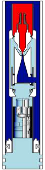
The downhole jet pump system manages three streams of fluid flow, 1. The power fluid injected from the surface, 2. The inflow from the well and 3. The discharge of the mixture of power fluid with produced fluid. The standard jet pump manages these three streams within the body of the jet pump. This pump design is very flexible allowing adaptation to standard well completion circulation sleeves, gas lift mandrels or concentric tubing well completions; however, it is limited to smaller nozzles which also limits lift capacity.
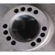
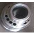
The high- volume jet pump provides large passages in the jet pump bottom hole assembly, (BHA) to manage inflow from the well leaving the pump to manage only two streams which allows the use of much larger nozzles. Figure 5.0 shows the twelve ½” passages that allow inflow from the well to the jet working section versus the twelve 3/8” holes in the jet pump that manage the same inflow. The high-volume jet pump has been known to produce more than 20,000 bpd.
High Volume Pump Specifications
|
Size |
2-3/8” |
2-7/8” |
3-1/2” |
|
BHA SEAL BORE |
1.87” |
2.31” |
2.81” |
|
BHA OD |
3.5” |
4.5” |
5.5” |
|
R Profile NO-GO |
1.822” |
2.260” |
2.759” |
Standard GPT TITAN Pump Specifications
|
Size |
2-3/8” |
2-7/8” |
3-1/2” |
|
BHA SEAL BORE |
1.87” |
2.31 |
2.81” |
|
BHA OD |
3.5” |
4.5” |
5.5” |
|
R profile NO-GO |
1.822” |
2.260” |
2.759” |
The standing valve seating nipple has an R profile.
Standard Jet Pump
The standard jet pump is the most flexible and versatile design because it manages the three flow streams within the body of the jet pump This minimizes requirements on ancillary well completion components.
Maximum production for any model jet pump is also limited by the casing diameter and capacity of fluid circulation considering that outflow is 200% to 400% greater than flow of power fluid to the jet pump.
Downhole Pressure Sensors
The new TITAN Jet pump offers a chamber that allows installation of a battery powered pressure and temperature gauge to monitor reservoir as the jet pump produces the well. Another option is to install sensors below the standing valve to monitor the same data while allowing build up test. The TITAN Jet pump well completion is also offered with permanent real time downhole gauges so the reservoir can be monitored, and operating conditions can be modified to produce the well at optimum rates.
Tolerance To Gas
The jet pump is tolerant to gas production because gas does not harm the jet pump and limited gas production reduces the weight of the fluid column being produced so it lowers the horsepower required to pump the fluid; However, very large volumes of gas can choke fluid production. The throat orifice flow area will handle fluid or gas, but large volumes of gas require large flow areas that may be too large for the jet pump.
Care should also be taken to monitor bubble point and the state of gas at the producing bottom hole pressure especially in casing free installations where all produced gas must flow through the pump.
Gassy wells can produce efficiently by separating the gas downhole and allowing the gas to flow to surface independent to fluid flow. Low pressure gassy reservoirs are pumped successfully and reliably with jet pumps around the globe with parallel tubing or concentric tubing completions. Flow rates and lift capacity may be limited by the smaller tubing sizes required in these completions.
The GPT document on jet pump design provides more insight into limitations of gas production in jet pumps.
Tolerance To Sand
The jet pump is used in concentric tubing completions to pump sand out of wells. The jet pump has been known to clean heavy drilling fluids and frac sand from wells and is commonly used to remove sand from a sanded well bore.
Jet pumps are often used to clean wells in unconsolidated sand formations.
Severe Dog Legs or Deviated Well Bores
Power transmission to the jet pump is accomplished by fluid that can go around any corner. The jet pump is offered in short designs to go around any severe dog leg.
Economy in Multiple Well Pads
The downhole jet pump is less than 15% of the total cost of a jet pump system so multiple wells that share common surface can greatly economize on the total cost per well.
Commitment to Excellence
Global Petroleum Technologies leads the field in jet pump innovation, research, development and built to suit engineering. Engineering is the key to successful reliable jet pumping.
At GPT, we go beyond the well data sheet. We look at lift requirements today and in the future as the reservoir changes. We look for life cycle solutions and will turn down an application if a jet pump is not the best solution.
Complete Product Line
The New Generation Jet is offered in the complete spectrum of jet pump solutions outlined in this catalog and in several of the old technology that has been supplied since the 70’s.
Jet Pump Models and Well Completion Solutions
The most common jet pump well completion has been covered above. Alternate jet pump models and well completions provide a wide range of solutions. The following provides a review of solutions that have proven over years; however, jet pumps offer wide flexibility where these models provide the basis for other special needs.
Casing Free Reverse Flow Well Completion
The same completion arrangement as in the casing free design, except that power fluid flows down the casing annulus with mixed exhaust power fluid with produced fluid flowing up the up the production tubing. This completion is commonly used in offshore applications where using water as power fluid and where hydrocarbons do not flow through the casing annulus or in cases of very corrosive fluids or heavy sand and debris.
A standing valve can also be set below the pump to prevent fluid loss during shut down.
The pump and standing valve are equipped with a locking profile, so the pump stays in place.

Sliding Sleeve Jet Specifications
|
Size |
2-3/8” |
2-7/8” |
3-1/2” |
|
SEAL OD |
1.87” |
2.31” |
2.81” |
Length and lock are provided to land in any sliding sleeve design.
Fixed Completions
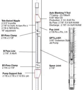
A jet pump can be connected to the bottom of tubing, small diameter tubing, coil tubing or hollow sucker rods and lowered in a well to seat on a seating nipple or insert pump anchor without the need to pull the completion to produce or test the well. A telescoping swivel sub and drain sub can provide a means to absorb tubing elongation when operating with high pressure fluid or draining the tubing to prevent a wet pulling job.
Fix pumps can be any standard that can be run inside the casing where the largest pump normally provides the greatest lift capacity.
Fixed Pump Specifications
|
Size |
2-3/8” |
2-7/8” |
3-1/2” |
|
BHA SEAL BORE |
1.87” |
2.312 |
2.812” |
|
BHA OD |
3.5” |
4.5” |
5.5” |
|
R profile NO-GO |
1.822” |
2.260” |
2.759” |
The standing valve seating nipple has an R profile.
Concentric Tubing Well Completion
The concentric tubing well completion is often the best solutions for low pressure gassy reservoir operating at Bottomhole pressures below the bubble point. A special 1.25” jet pump with 2.2” OD BHA can be attached to small diameter pipe or coil tubing and run inside 2-7/8” production tubing or larger and set below perforations to optimize gas separation by injecting power fluid down the small diameter tubing to discharge mixed exhaust power fluid and produced medium up the production tubing. Gas in liberated state and separated downhole can flow up the casing annulus. The small diameter pipe limits the size nozzles that can be run in these completions so produced volume and lift capacity is limited. Production is normally less than 500 bfpd.
Concentric Pump Specifications
|
Size |
HV 1-1/4” |
HV 1-1/2” |
|
BHA SEAL BORE |
1.25” |
1.525” |
|
BHA OD |
2.5” |
2.75” |
|
R profile NO-GO |
Internal |
1.87” |
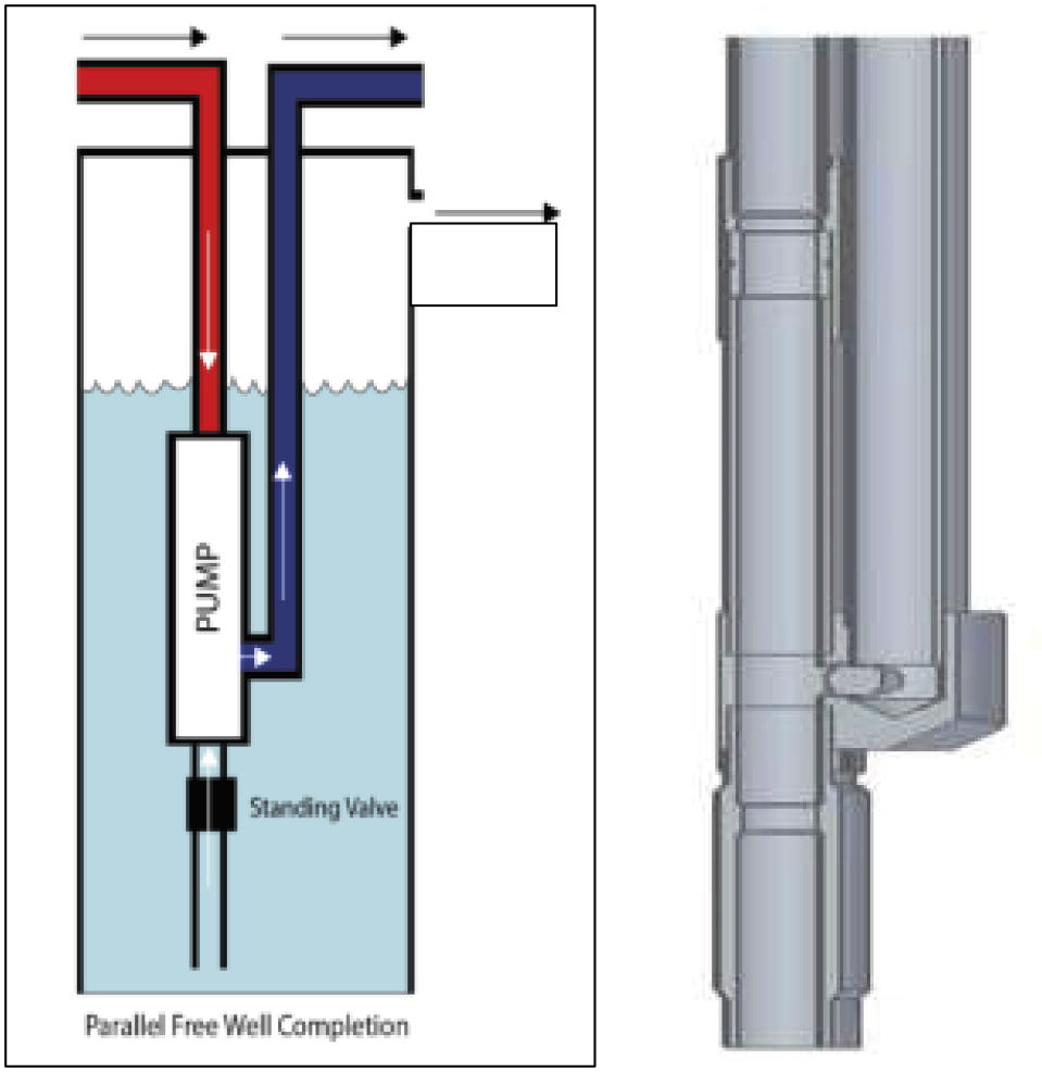
Parallel Free Well Completion
High volume Gassy Low-Pressure reservoirs are best produced with a parallel free well completion where the casing size permits installation of tubing sizes that can produce higher volumes than the concentric tubing completion.
In parallel free well completions, power fluid is injected down the main or long tubing string where the jet pump is located and mixed exhaust power fluid with produced medium flow up the side string or short tubing string. The pump can be placed below perforations to optimize gas separation allowing liberated gas to flow up the casing annulus. Maximum production rates and lift capacities are dependent on casing and tubing size.
Concentric pumps can be run with a bottom hole assembly so the pump can be circulated to the surface for modification or repair or directly threaded to the tubing where a larger pump can be run for maximum lift capacity.
Gas Lift Mandrel or Perforated Tubing
The jet pump can be straddled across a gas lift mandrel when water production increases and/ or reservoir pressure declines resulting in increased slippage or fall back. The same solutions can be provided with tubing is perforated.
Gas Lift / Straddle Pump Specifications
|
Size |
2-3/8” |
2-7/8” |
3-1/2” |
|
BHA SEAL BORE |
1.87” |
2.312 |
2.812” |
|
BHA OD |
3.5” |
4.5” |
5.5” |
|
R profile NO-GO |
1.822” |
2.260” |
2.759” |
The standing valve seating nipple has an R profile.
The jet pump’s flexibility allows it to be adapted to well testing strings to allow pumping while performing well interventions, PLT’s or other testing or cleaning services. The following are several examples of jet pump testing assemblies.
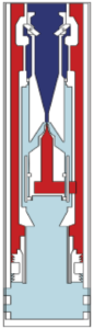
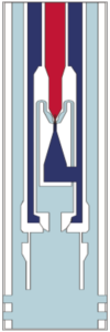
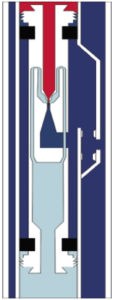
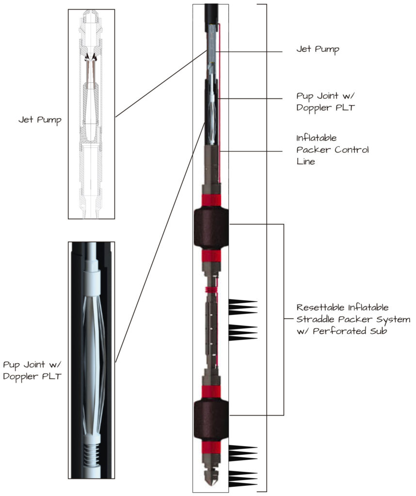
Straddle Inflatable Packer Logging Jet Assemblies
Straddle jet pump solutions can also be used to straddle a jet pump across perforations with inflatable packers to log production from isolated zones where power fluid is used to set packers while pumping the zone. Packers release when power fluid pressure is reduced to allow repositioning and resetting to log a separate zone.
Miller Logging Jet Testing Assembly
The Jet pump can be straddled between two inflatable packers and actuated with the power fluid injected to the jet pump that allows pumping the specific zone while testing.
Hydrolog Jet Pump
The HYDROLOG jet pump is a Y-Tool jet pump that can be equipped with a wireline logging plug to allow manipulation of logging tools to target zones while pumping the well with a jet pump. Requires a casing packer so mixed exhaust power fluid with produced medium can flow up the casing annulus.
HYDROLOG Pump Specifications
|
Pump Size |
2” |
|
Y-TOOL OD |
5.5” |
Y-Tool Jet Pump for Esp Stand By
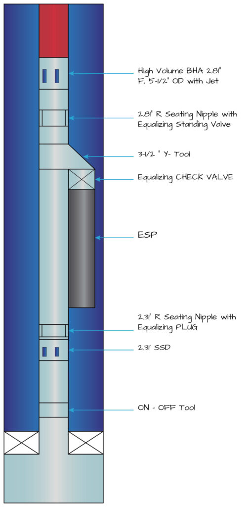
The Jet Pump is also available to land on a sliding sleeve below or above a Y-Tool to serve as a back- up support for electric submersible pump (ESP) applications.
Pulling the ESP for service is sometimes delayed due to weather or a lack of pulling units. A jet pump can be set in the sliding sleeve and ESP passage plugged to continue production while eliminating down time.
Low Pressure Gassy Reservoirs
Low pressure gassy reservoirs have historically been produced with beam pumps allowing gas to flow up the casing annulus. These wells often operate at producing bottom hole pressures below the bubble point where most of the gas is liberated or in free state as it comes out of the perforations downhole. There are several options of Downhole separators to improve pump performance.
These reservoirs often include high sand production, deviated or severe dog legs that result in frequent failures that put a crunch on the business of producing the well.
Jet pumps are often considered but too frequently with the most common casing free well completion where gas accumulates under the packer where fluid production falls below acceptable levels.
Solutions with jet pumps for these reservoirs require well completions that provide downhole gas separation and casing annulus gas flow that has proven successful with beam pumps. Completion alternatives depend on flow rates and casing size. The fixed and concentric well completions mentioned above are reliable for lower production rates.
High volume Gassy Low-Pressure reservoirs are best produced with a parallel free well completion where casing size permits installation of larger tubing sizes.
Parallel Free Well Completion
In parallel free well completions, power fluid is injected down the main or long tubing string where the jet pump is located and mixed exhaust power fluid with produced medium flow up the side string or short tubing string. The pump can be placed below perforations to optimize gas separation allowing liberated gas to flow up the casing annulus. Maximum production rates and lift capacities are dependent on casing and tubing size.
There are few oil fields in the world that use the parallel free completion to produce in excess of 1500 bfpd. These have been found to be the most reliable lift method for production ranges from 100 bpd to near 2000 bpd and GOR to 6000 scf/bbl. The BHA is normally located below perforations to optimize gas separation and the jet pump keeps the well bore clean.
Parallel Pump Specifications
|
Size |
2-3/8” x 2-3/8” |
2-7/8” X 2-3/8” |
|
BHA SEAL BORE |
1.87” |
2.31” |
|
BHA OD |
5.800” |
7.125” |
|
R profile NO-GO |
1.822” |
2.260” |
The standing valve seating nipple has an R profile.
The new generation parallel BHA and jet pump system aligns communication ports while offering options of standing valve designs and landing positions to accommodate severe sand production while maintaining higher volume lift capacity or less horsepower usage per barrel produced.
In addition to discharge communication port, the bottom of the GPT New Gen BHA is opened to a full 2.31” ID for full ID flow area from the well.
The 2.31” F profile standard on GPT BHA’s permit installation of reverse flow jet pumps. This is useful when starting a well that may have excessive sand production, the standard circulation may dump sand in the casing annulus that could results in a fish.
GPT THROAT AND NOZZLE SIZES
| GPT TITAN Nozzle Selection | GPT C Nozzle and Throat Selection |
|
Nozzle |
Throat |
Nozzle |
Throat |
||||
|
Number |
Area in² |
Throat |
Area in² |
Number |
Area in² |
Number |
Area in² |
|
1 |
0.0024 |
1 |
0.0064 |
DD |
0.0016 |
000 |
0.0044 |
|
2 |
0.0031 |
2 |
0.0081 |
CC |
0.0028 |
00 |
0.0071 |
|
3 |
0.0039 |
3 |
0.0104 |
BB |
0.0038 |
0 |
0.0104 |
|
4 |
0.0050 |
4 |
0.0131 |
A |
0.0055 |
1 |
0.0143 |
|
5 |
0.0064 |
5 |
0.0167 |
B |
0.0095 |
2 |
0.0189 |
|
6 |
0.0081 |
6 |
0.0212 |
C |
0.0123 |
3 |
0.0241 |
|
7 |
0.0103 |
7 |
0.0271 |
C+ |
0.0 |
4 |
0.0314 |
|
8 |
0.0131 |
8 |
0.0346 |
D |
0.0177 |
5 |
0.0380 |
|
9 |
0.0167 |
9 |
0.0441 |
E |
0.0241 |
6 |
0.0452 |
|
10 |
0.0212 |
10 |
0.0562 |
F |
0.0314 |
7 |
0.0531 |
|
11 |
0.0271 |
11 |
0.0715 |
G |
0.0452 |
8 |
0.0661 |
|
12 |
0.0346 |
12 |
0.0910 |
H |
0.0661 |
9 |
0.0804 |
|
13 |
0.0441 |
13 |
0.1159 |
I |
0.0855 |
10 |
0.0962 |
|
14 |
0.0562 |
14 |
0.1476 |
J |
0.1257 |
11 |
0.1195 |
|
15 |
0.0715 |
15 |
0.1879 |
K |
0.1590 |
12 |
0.1452 |
|
16 |
0.0910 |
16 |
0.2392 |
L |
0.1963 |
13 |
0.1772 |
|
17 |
0.1159 |
17 |
0.3046 |
M |
0.2463 |
14 |
0.2165 |
|
18 |
0.1476 |
18 |
0.3878 |
N |
0.3117 |
15 |
0.2606 |
|
19 |
0.01879 |
19 |
0.4938 |
P |
0.3848 |
16 |
0.3127 |
|
20 |
0.2392 |
20 |
0.6287 |
|
|
17 |
0.3750 |
GPT A THRIAT AND NOZZLE ANNULUS AREAS
|
GPT TITAN Throat Annulus Area In² |
|
Nozzle |
X |
A |
B |
C |
D |
E |
|
|
1 |
|
0.0040 |
0.0057 |
0.0080 |
0.0108 |
0.0144 |
|
|
2 |
0.0033 |
0.0050 |
0.0073 |
0.0101 |
0.0137 |
0.0183 |
|
|
3 |
0.0042 |
0.0065 |
0.0093 |
0.0129 |
0.0175 |
0.0233 |
|
|
4 |
0.0054 |
0.0082 |
0.0118 |
0.0164 |
0.0222 |
0.0296 |
|
|
5 |
0.0068 |
0.0104 |
0.0150 |
0.0208 |
0.0282 |
0.0377 |
|
|
6 |
0.0087 |
0.0133 |
0.0191 |
0.0265 |
0..0360 |
0.0481 |
|
|
7 |
0.0111 |
0.0169 |
0.0243 |
0.0338 |
0.0459 |
0.0612 |
|
|
8 |
0.0141 |
0.0215 |
0.0310 |
0.0431 |
0.0584 |
0.0779 |
|
|
9 |
0.0179 |
0.0274 |
0.0395 |
0.0548 |
0.0743 |
0.0992 |
|
|
10 |
0.0229 |
0.0350 |
0.0503 |
0.0698 |
0.0947 |
0.1264 |
|
|
11 |
0.0291 |
0.0444 |
0.0639 |
0.0888 |
0.1205 |
0.1608 |
|
|
12 |
0.0369 |
0.0564 |
0.0813 |
0.1130 |
0.1533 |
0.2046 |
|
|
13 |
0.0469 |
0.0718 |
0.1035 |
0.1438 |
0.1951 |
0.2605 |
|
|
14 |
0.0597 |
0.0914 |
0.1317 |
0.1830 |
0.2484 |
0.3316 |
|
|
15 |
0.0751 |
0.1164 |
0.1677 |
0.2331 |
0.3163 |
0.4223 |
|
|
16 |
0.0969 |
0.1482 |
0.2136 |
0.2968 |
0.4028 |
0.5377 |
|
|
17 |
0.1234 |
0.1888 |
0.2720 |
0.3779 |
0.5128 |
|
|
|
18 |
0.1571 |
0.2403 |
0.3463 |
0.4812 |
|
|
|
|
19 |
0.2000 |
0..3060 |
0.4409 |
|
|
|
|
|
20 |
0.2546 |
0.03896 |
|
|
|
|
|
JET PUMP NOZZLE FLOW RATES
The following are nozzle Flow rates using water for power fluid.
GPT TITAN SIZES 7 NOZZLE
|
PUMP |
SURFACE POWER FLUID PRESSURE, PSI |
|||||
|
DEPTH FT. |
INTAKE PRESSURE PSI |
2000 |
2500 |
3000 |
3500 |
4000 |
|
POWER FLUID RATE BPD |
||||||
|
4000 |
1500 |
650 |
692 |
752 |
804 |
858 |
|
1000 |
696 |
752 |
804 |
858 |
906 |
|
|
500 |
756 |
804 |
858 |
906 |
958 |
|
|
6000 |
1500 |
750 |
794 |
844 |
894 |
944 |
|
1000 |
797 |
844 |
894 |
944 |
984 |
|
|
500 |
850 |
894 |
944 |
984 |
1030 |
|
|
8000 |
1500 |
846 |
884 |
930 |
975 |
1016 |
|
1000 |
897 |
930 |
975 |
1016 |
1060 |
|
|
500 |
955 |
975 |
1016 |
1060 |
1090 |
|
|
10,000 |
1500 |
873 |
914 |
966 |
1004 |
1048 |
|
1000 |
932 |
966 |
1004 |
1048 |
1090 |
|
|
500 |
968 |
1004 |
1048 |
1090 |
1128 |
|
|
12,000 |
1500 |
966 |
993 |
1036 |
1078 |
1116 |
|
1000 |
990 |
1036 |
1078 |
1116 |
1152 |
|
|
500 |
1053 |
1078 |
1116 |
1152 |
1196 |
|
|
14,000 |
1500 |
1042 |
1066 |
1106 |
1142 |
1186 |
|
1000 |
1083 |
1106 |
1142 |
1186 |
1218 |
|
|
500 |
1113 |
1142 |
1186 |
1218 |
1240 |
|
GPT TITAN Size 8 Nozzle
|
PUMP |
SURFACE POWER FLUID PRESSURE, PSI |
|||||
|
DEPTH FT. |
INTAKE PRESSURE PSI |
2000 |
2500 |
3000 |
3500 |
4000 |
|
POWER FLUID RATE BPD |
||||||
|
4000 |
1500 |
798 |
876 |
956 |
1022 |
1094 |
|
1000 |
876 |
956 |
1022 |
1094 |
1154 |
|
|
500 |
956 |
1022 |
1094 |
1154 |
1218 |
|
|
6000 |
1500 |
938 |
1004 |
1074 |
1136 |
1196 |
|
1000 |
1004 |
1074 |
1136 |
1196 |
1256 |
|
|
500 |
1074 |
1136 |
1196 |
1256 |
1310 |
|
|
8000 |
1500 |
1054 |
1124 |
1186 |
1240 |
1292 |
|
1000 |
1124 |
1186 |
1240 |
1292 |
1348 |
|
|
500 |
1186 |
1240 |
1292 |
1348 |
1390 |
|
|
10,000 |
1500 |
1105 |
1164 |
1224 |
1282 |
1336 |
|
1000 |
1164 |
1224 |
1282 |
1336 |
1382 |
|
|
500 |
1224 |
1282 |
1336 |
1382 |
1432 |
|
|
12,000 |
1500 |
1210 |
1262 |
1222 |
1376 |
1426 |
|
1000 |
1262 |
1222 |
1376 |
1426 |
1472 |
|
|
500 |
1222 |
1376 |
1426 |
1472 |
1516 |
|
|
14,000 |
1500 |
1302 |
1358 |
1410 |
1456 |
1502 |
|
1000 |
1358 |
1410 |
1456 |
1502 |
1554 |
|
|
500 |
1410 |
1456 |
1502 |
1554 |
1592 |
|
GPT TITAN Size 9 Nozzle
|
PUMP |
SURFACE POWER FLUID PRESSURE, PSI |
|||||
|
DEPTH FT. |
INTAKE PRESSURE PSI |
2000 |
2500 |
3000 |
3500 |
4000 |
|
POWER FLUID RATE BPD |
||||||
|
4000 |
1500 |
1006 |
1013 |
1216 |
1306 |
1384 |
|
1000 |
1013 |
1216 |
1306 |
1348 |
1462 |
|
|
500 |
1216 |
1306 |
1348 |
1462 |
1554 |
|
|
6000 |
1500 |
1184 |
1278 |
1364 |
1444 |
1524 |
|
1000 |
1278 |
1364 |
1444 |
1524 |
1598 |
|
|
500 |
1364 |
1444 |
1524 |
1598 |
1668 |
|
|
8000 |
1500 |
1344 |
1428 |
1504 |
1577 |
1642 |
|
1000 |
1428 |
1504 |
1577 |
1642 |
1716 |
|
|
500 |
1504 |
1577 |
1642 |
1716 |
1776 |
|
|
10,000 |
1500 |
1402 |
1482 |
1552 |
1624 |
1694 |
|
1000 |
1482 |
1552 |
1624 |
1694 |
1762 |
|
|
500 |
1552 |
1624 |
1694 |
1762 |
1828 |
|
|
12,000 |
1500 |
1532 |
1606 |
1674 |
1746 |
1804 |
|
1000 |
1606 |
1674 |
1746 |
1804 |
1868 |
|
|
500 |
1674 |
1746 |
1804 |
1868 |
1926 |
|
|
14,000 |
1500 |
1658 |
1722 |
1790 |
1854 |
1916 |
|
1000 |
1722 |
1790 |
1854 |
1916 |
1972 |
|
|
500 |
1790 |
1854 |
1916 |
1972 |
2024 |
|
GPT TITAN Size 10 Nozzle
|
PUMP |
SURFACE POWER FLUID PRESSURE, PSI |
|||||
|
DEPTH FT. |
INTAKE PRESSURE PSI |
2000 |
2500 |
3000 |
3500 |
4000 |
|
POWER FLUID RATE BPD |
||||||
|
4000 |
1500 |
1286 |
1418 |
1546 |
1656 |
1762 |
|
1000 |
1418 |
1546 |
1656 |
1762 |
1864 |
|
|
500 |
1546 |
1656 |
1762 |
1864 |
1966 |
|
|
6000 |
1500 |
1512 |
1626 |
1736 |
1840 |
1934 |
|
1000 |
1626 |
1736 |
1840 |
1934 |
2030 |
|
|
500 |
1736 |
1840 |
1934 |
2030 |
2116 |
|
|
8000 |
1500 |
1708 |
1816 |
1914 |
2004 |
2094 |
|
1000 |
1816 |
1914 |
2004 |
2094 |
2182 |
|
|
500 |
1914 |
2004 |
2094 |
2182 |
2268 |
|
|
10,000 |
1500 |
1782 |
1882 |
1982 |
2072 |
2156 |
|
1000 |
1882 |
1982 |
2072 |
2156 |
2244 |
|
|
500 |
1982 |
2072 |
2156 |
2244 |
|
|
|
12,000 |
1500 |
1952 |
2046 |
2136 |
2220 |
2302 |
|
1000 |
2046 |
2136 |
2220 |
2302 |
2378 |
|
|
500 |
2136 |
2220 |
2302 |
2378 |
5458 |
|
|
14,000 |
1500 |
2114 |
2194 |
2278 |
2358 |
2438 |
|
1000 |
2194 |
2278 |
2358 |
2438 |
2508 |
|
|
500 |
2278 |
2358 |
2438 |
2508 |
2582 |
|
GPT TITAN Size 11 Nozzle
|
PUMP |
SURFACE POWER FLUID PRESSURE, PSI |
|||||
|
DEPTH FT. |
INTAKE PRESSURE PSI |
2000 |
2500 |
3000 |
3500 |
4000 |
|
POWER FLUID RATE BPD |
||||||
|
4000 |
1500 |
1638 |
1804 |
1964 |
2114 |
2246 |
|
1000 |
1804 |
1964 |
2114 |
2246 |
2374 |
|
|
500 |
1964 |
2114 |
2246 |
2374 |
2498 |
|
|
6000 |
1500 |
1928 |
2076 |
2214 |
2346 |
2464 |
|
1000 |
2076 |
2214 |
2346 |
2464 |
2584 |
|
|
500 |
2214 |
2346 |
2464 |
2584 |
2696 |
|
|
8000 |
1500 |
2172 |
2308 |
2438 |
2558 |
2666 |
|
1000 |
2308 |
2438 |
2558 |
2666 |
2774 |
|
|
500 |
2438 |
2558 |
2666 |
2774 |
2886 |
|
|
10,000 |
1500 |
2278 |
2408 |
2526 |
2636 |
2748 |
|
1000 |
2408 |
2526 |
2636 |
2748 |
2858 |
|
|
500 |
2526 |
2636 |
2748 |
2858 |
2954 |
|
|
12,000 |
1500 |
2492 |
2606 |
2718 |
2824 |
2930 |
|
1000 |
2606 |
2718 |
2824 |
2930 |
3030 |
|
|
500 |
2718 |
2824 |
2930 |
3030 |
3124 |
|
|
14,000 |
1500 |
2690 |
2796 |
2906 |
3008 |
3102 |
|
1000 |
2796 |
2906 |
3008 |
3102 |
3192 |
|
|
500 |
2906 |
3008 |
3102 |
3192 |
3286 |
|
GPT TITAN Size 12 Nozzle
|
PUMP |
SURFACE POWER FLUID PRESSURE, PSI |
|||||
|
DEPTH FT. |
INTAKE PRESSURE PSI |
2000 |
2500 |
3000 |
3500 |
4000 |
|
POWER FLUID RATE BPD |
||||||
|
4000 |
1500 |
2094 |
2318 |
2512 |
2706 |
2876 |
|
1000 |
2318 |
2512 |
2706 |
2876 |
3046 |
|
|
500 |
2512 |
2706 |
2876 |
3046 |
3200 |
|
|
6000 |
1500 |
2466 |
2658 |
2836 |
3000 |
3158 |
|
1000 |
2658 |
2836 |
3000 |
3158 |
3310 |
|
|
500 |
2836 |
3000 |
3158 |
3310 |
3458 |
|
|
8000 |
1500 |
2782 |
2952 |
3114 |
3270 |
3412 |
|
1000 |
2952 |
3114 |
3270 |
3412 |
3552 |
|
|
500 |
3114 |
3270 |
3412 |
3552 |
3692 |
|
|
10,000 |
1500 |
2914 |
3074 |
3230 |
3376 |
3518 |
|
1000 |
3074 |
3230 |
3376 |
3518 |
3658 |
|
|
500 |
3230 |
3376 |
3518 |
3658 |
3784 |
|
|
12,000 |
1500 |
3184 |
3338 |
3484 |
3618 |
3754 |
|
1000 |
3338 |
3484 |
3618 |
3754 |
3880 |
|
|
500 |
3484 |
3618 |
3754 |
3880 |
4008 |
|
|
14,000 |
1500 |
3448 |
3586 |
3714 |
3842 |
3972 |
|
1000 |
3586 |
3714 |
3842 |
3972 |
4094 |
|
|
500 |
3714 |
3842 |
3972 |
4094 |
4210 |
|
GPT TITAN Size 13 Nozzle
|
PUMP |
SURFACE POWER FLUID PRESSURE, PSI |
|||||
|
DEPTH FT. |
INTAKE PRESSURE PSI |
2000 |
2500 |
3000 |
3500 |
4000 |
|
POWER FLUID RATE BPD |
||||||
|
4000 |
1500 |
2664 |
2944 |
3206 |
3442 |
3668 |
|
1000 |
2944 |
3206 |
3442 |
3668 |
3878 |
|
|
500 |
3206 |
3442 |
3668 |
3878 |
4078 |
|
|
6000 |
1500 |
3132 |
3378 |
3602 |
3818 |
4022 |
|
1000 |
3378 |
3602 |
3818 |
4022 |
4218 |
|
|
500 |
3605 |
3818 |
4022 |
4218 |
4396 |
|
|
8000 |
1500 |
3544 |
3766 |
3966 |
4166 |
4348 |
|
1000 |
3766 |
3966 |
4166 |
4348 |
4524 |
|
|
500 |
3966 |
4166 |
4348 |
4524 |
4698 |
|
|
10,000 |
1500 |
3702 |
3918 |
4114 |
4300 |
4480 |
|
1000 |
3918 |
4114 |
4300 |
4480 |
4658 |
|
|
500 |
4114 |
4300 |
4480 |
4658 |
4822 |
|
|
12,000 |
1500 |
4060 |
4250 |
4436 |
4606 |
4274 |
|
1000 |
4250 |
4436 |
4606 |
4274 |
4940 |
|
|
500 |
4436 |
4606 |
4274 |
4940 |
5094 |
|
|
14,000 |
1500 |
4387 |
4594 |
4734 |
4892 |
5052 |
|
1000 |
4594 |
4734 |
4892 |
5052 |
5210 |
|
|
500 |
4734 |
4892 |
5052 |
5210 |
5360 |
|
GPT TITAN Size 14 Nozzle
|
PUMP |
SURFACE POWER FLUID PRESSURE, PSI |
|||||
|
DEPTH FT. |
INTAKE PRESSURE PSI |
2000 |
2500 |
3000 |
3500 |
4000 |
|
POWER FLUID RATE BPD |
||||||
|
4000 |
1500 |
3386 |
3744 |
4072 |
4378 |
4666 |
|
1000 |
3744 |
4072 |
4378 |
4666 |
4930 |
|
|
500 |
4072 |
4378 |
4666 |
4930 |
5188 |
|
|
6000 |
1500 |
3990 |
4300 |
4588 |
4860 |
5114 |
|
1000 |
4300 |
4588 |
4860 |
5114 |
5364 |
|
|
500 |
4588 |
4860 |
5114 |
5364 |
5592 |
|
|
8000 |
1500 |
4516 |
4788 |
5050 |
5296 |
5538 |
|
1000 |
4788 |
5050 |
5296 |
5538 |
5764 |
|
|
500 |
5050 |
5296 |
5538 |
5764 |
5980 |
|
|
10,000 |
1500 |
4712 |
4982 |
5234 |
5474 |
5704 |
|
1000 |
4982 |
5234 |
5474 |
5704 |
5924 |
|
|
500 |
5234 |
5474 |
5704 |
5924 |
6134 |
|
|
12,000 |
1500 |
5162 |
5408 |
5642 |
5868 |
6078 |
|
1000 |
5408 |
5642 |
5868 |
6078 |
6282 |
|
|
500 |
5642 |
5868 |
6078 |
6282 |
6484 |
|
|
14,000 |
1500 |
5580 |
5808 |
6024 |
6232 |
6438 |
|
1000 |
5808 |
6024 |
6232 |
6438 |
6630 |
|
|
500 |
6024 |
6232 |
6438 |
6630 |
6826 |
|
GPT TITAN Size 15 Nozzle
|
PUMP |
SURFACE POWER FLUID PRESSURE, PSI |
|||||
|
DEPTH FT. |
INTAKE PRESSURE PSI |
2000 |
2500 |
3000 |
3500 |
4000 |
|
POWER FLUID RATE BPD |
||||||
|
4000 |
1500 |
4312 |
4768 |
5184 |
5576 |
5936 |
|
1000 |
4768 |
5184 |
5576 |
5936 |
6276 |
|
|
500 |
5184 |
5576 |
5936 |
6276 |
6596 |
|
|
6000 |
1500 |
5076 |
5474 |
5840 |
6182 |
6516 |
|
1000 |
5474 |
5840 |
6182 |
6516 |
6826 |
|
|
500 |
5840 |
6182 |
6516 |
6826 |
7126 |
|
|
8000 |
1500 |
5748 |
6098 |
6424 |
6746 |
7048 |
|
1000 |
6098 |
6424 |
6746 |
7048 |
7336 |
|
|
500 |
6424 |
6746 |
7048 |
7336 |
7614 |
|
|
10,000 |
1500 |
6006 |
6340 |
6660 |
6966 |
7254 |
|
1000 |
6340 |
6660 |
6966 |
7254 |
7536 |
|
|
500 |
6660 |
6966 |
7254 |
7536 |
7808 |
|
|
12,000 |
1500 |
6579 |
6888 |
7180 |
7468 |
7734 |
|
1000 |
6888 |
7180 |
7468 |
7734 |
8002 |
|
|
500 |
7180 |
7468 |
7734 |
8002 |
8254 |
|
|
14,000 |
1500 |
7104 |
7388 |
7668 |
7932 |
8188 |
|
1000 |
7388 |
7668 |
7932 |
8188 |
8438 |
|
|
500 |
7668 |
7932 |
8188 |
8438 |
8684 |
|
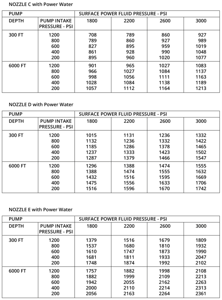
JET PUMP C NOZZLE FLOW RATES
NOZZLE C with Power Water
Equations, Conversion and Useful Information
- 1 Cubic meter per day = 8.38641436 Fluid barrels per day.
- 1 Barrel = 159 liters = 42 gallons
- 1 Bpd = .159 cubic meters pe day
- 1 Barrel = 5.61458
- 1 Horsepower -0.7457 Kilowatts
- HP = Torque x RPM / 5252
- GOR: 1 scf/bbl = 0.18 m3/m3
- Hydraulic horsepower = (pressure differential x bpd) /58,800
Net Positive Suction Head for GPT Plunger Pumps
NPSHR = Function of Pp + Pv + Pf – Pa + Ha
Where
- NPSHR: Net Positive Suction Head Required
- Pa: Atmospheric pressure in psia (+/- 14 psia)
- Pv: Vapor Pressure of the fluid, in psia
- Pf: Pressure drop due to friction in suction piping and fittings, in psia (normally below .1 psig= 14.1 psig)
- Ha: Acceleration head in feet. (see calculation below)
- Pp: Pressure required by pump above vapor pressure to fill pump with acceptable efficiency, in psi. A factor of pump internals such as valve springs, internal passages etc…) The pump manufacturer specifies 3.5 psig = 17.5 psia
Acceleration Head: Ha= (CLNQ) / D2
- C: Triplex = .000598, C: Quintuplex = .000362
- L: Suction tubing length in feet
- N: rpm pump speed
- Q: gpm pump capacity at operating speed
- D: suction tubing diameter